
Circuit Protection as Engineering Practice: Fault Types, Device Families and Coordination
Ask a design team what keeps a power system alive and the answer usually involves conservative margins, carefully specified parts or good workmanship. Much less often does it involve the hardware whose only task is to stop current. That silence is the point: when protection is doing its job, nothing visible happens at all. The aim here is to treat circuit protection as a transferable engineering practice rather than a product category — the fault mechanisms that stress residential, commercial, industrial and utility networks, the device families that answer each mechanism, and the coordination discipline that decides whether a system trips precisely or trips helplessly.
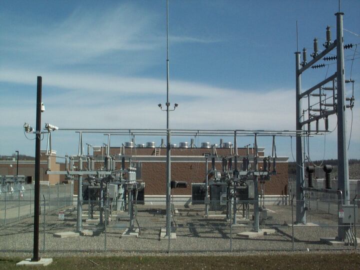 Figure 1: Utility-scale substation equipment, where protective schemes decide whether a local disturbance stays local or becomes a wide-area event. Courtesy: CDM Smith
What this guide is meant to deliver
- Recognise the four fault classes — overload, short circuit, ground fault and overvoltage — as design inputs rather than as accidents, and connect each to the protection function that neutralises it.
- Tell the main device families apart: fuses, circuit breakers, ground fault circuit interrupters, arc fault circuit interrupters, surge protection devices and medium-voltage relaying, including how each senses a problem and where each belongs.
- Apply coordination as a reviewable method: how selective settings and time-current curves keep a small fault small, and how digital relays plus automation extend that logic across a network.
Scope: the parts of an electrical defence that generalists own
The components discussed are the ones that appear in nearly every schematic, irrespective of industry: fuses, circuit breakers, motor starters and relays. Alongside them sit three devices that have moved from code-driven specialties to everyday design decisions — GFCIs, AFCIs and SPDs. As circuits get denser and more sensitive, the tolerance for unreviewed protection shrinks; a fault that once damaged one machine now interrupts process equipment, data hardware and the schedules attached to them. Protection is foundational, routinely overlooked, and quietly responsible for everything from a single appliance to an interconnected grid.
Four fault mechanisms behind every protective device
Electricity is easiest to reason about through its hydraulic analogy: current behaves like flow rate, voltage like the pressure driving that flow, and resistance like anything obstructing it. A healthy circuit keeps the three in balance. Every fault below is a breach of that balance, and each breach damages in a different way and on a different timescale — which is exactly why no single device type covers them all.
An overload is cumulative rather than dramatic. It appears when a circuit keeps drawing beyond its rated limit, typically because too much equipment shares one path, and the heat accumulated over time attacks insulation and plastic parts. That slow attack is the leading contributor to long-term electrical fires. A short circuit is the opposite: a low-resistance path, often frayed wiring bridging two conductors, collapses resistance toward zero and current rises to explosive values in an instant, producing violent arcing and immediate destruction of whatever is in the way.
A ground fault occurs whenever current finds an unintended route to earth, for example through a metal enclosure; the danger is a person completing that path and carrying current through the body, which can be severe or fatal. Overvoltage is a pressure event rather than a flow event: lightning or utility switching drives a sudden rise that can erase sensitive semiconductor components instantly.
| Fault class | Mechanism | Dominant consequence | Protection function that answers it |
|---|---|---|---|
| Overload | Current stays above the rated limit of the circuit. | Heat accumulates, insulation and plastic degrade; leading long-term fire cause. | Time-delayed thermal tripping or element melting. |
| Short circuit | A low-resistance bridge between conductors drives current to extreme values. | Violent arcing and near-instant equipment loss. | Instantaneous magnetic interruption or current-limiting fusing. |
| Ground fault | Current leaves the intended path for earth, often through enclosures. | Shock hazard to personnel, potentially fatal. | Imbalance detection: GFCI or relayed ground protection. |
| Overvoltage | Voltage spikes from lightning or utility switching. | Instant destruction of sensitive electronics. | Clamping and diversion by SPD. |
Left uncontrolled, these four conditions convert into equipment damage, unplanned downtime and injury. Protection devices exist specifically to intervene before that conversion finishes.
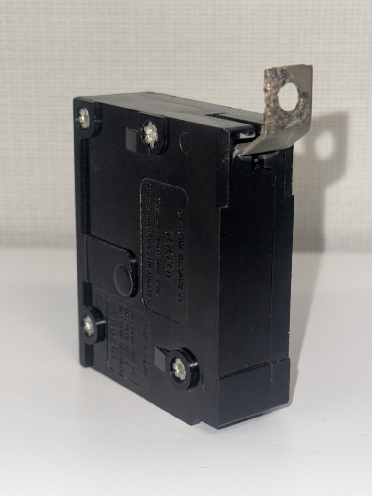 Figure 2: Hardware damaged by abnormal operating conditions — a reminder of the risks that sit invisibly inside any electrical system. Courtesy: CDM Smith
Overcurrent protection: the two core device families
From a single branch circuit to a massive grid, overcurrent protection devices (OCPDs) carry the basic duty of opening a circuit automatically once current passes its safe design limit. In doing so they spare conductors and equipment and remove the fire consequence of sustained fault current. The field splits into two families: fuses and circuit breakers.
Fuses: protection through designed, sacrificial failure
A fuse is intentionally the weakest element in the path. Its element — a calibrated conductive wire or strip — melts once resistive, or Joule, heating raises its temperature to the melting point. If current exceeds the fuse's ampere rating for a sufficient duration, the element blows, an open circuit appears, and the faulty section is isolated whether the trigger was a short circuit or a prolonged overload.
- Cartridge fuses: cylindrical elements housed in an insulating fibre or ceramic body, typical in control panels and motor circuits.
- Blade fuses, also called automotive fuses: a non-encased metal strip form used on low-voltage DC systems.
- High-voltage fuses: applied in utility distribution and substation equipment, often packed with arc-quenching material such as borax or interrupting in compressed gas such as sulfur hexafluoride (SF6) so the high-energy arc is safely extinguished.
With no moving parts to wear out, a fuse is simple, reliable, inexpensive and extremely fast under short-circuit conditions — the reason it survives everywhere from a small DC branch to a substation. Its trade-off is single use: after clearing a fault it must be replaced, and that replacement is maintenance labour and downtime.
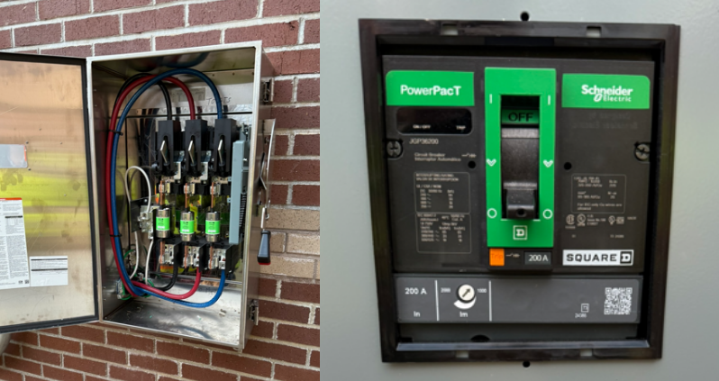 Figure 3: Overcurrent protection devices — a fused disconnect switch and a molded-case circuit breaker — that interrupt excessive current to shield conductors and equipment. Courtesy: CDM Smith
Circuit breakers: interruption that can be reused
A breaker performs the same protective role as a fuse but as an electromechanical device that can be closed again once the cause is corrected. That reset capability buys operational flexibility and lower maintenance cost in circuits that must return to service quickly.
Two mechanisms divide the work:
- Thermal trip for overload: a bimetallic strip composed of two metals with unequal thermal expansion rates bends under the heat of sustained overcurrent and mechanically trips the contacts. Because the strip must warm and deform first, the response is deliberately time-delayed, letting harmless temporary spikes pass while still clearing real overloads.
- Magnetic trip for short circuit: the surge of a short circuit passes through a solenoid, also called an electromagnet, and the resulting field instantly pulls an armature, bypassing the thermal path and opening the contacts in milliseconds. That speed is what limits the damage of a catastrophic fault.
Breakers are scaled and specialised by the fault current they must interrupt:
- Molded-case circuit breakers: rugged insulating housings for main distribution feeders and heavy industrial loads, frequently with adjustable trip settings.
- Miniature circuit breakers: compact devices for lighting panels, usually without adjustable settings.
- Air, gas and vacuum circuit breakers: high-voltage transmission and distribution service, using techniques such as SF6 gas or vacuum interruption to extinguish the high-energy arc.
Against a fuse, a breaker adds reset, customisable selective coordination through settings, and often integrated ground-fault and arc-fault functions. In exchange it brings more complexity, more cost, and a requirement for periodic testing so the mechanical trip mechanism stays credible.
Side-by-side for a general design review
| Review question | Fuse | Circuit breaker |
|---|---|---|
| How is the fault cleared? | Element melts from resistive heating; permanent open circuit. | Thermal strip or magnetic solenoid trips the contacts. |
| After the fault? | Replace the fuse. | Reset once the cause is corrected. |
| Response to short circuit | Fast-acting and current-limiting. | Instantaneous magnetic trip within milliseconds. |
| Mechanical complexity | None; no moving parts. | Mechanism requires periodic testing. |
| Adjustability | Fixed by selection of rating. | Settings available for selective coordination and added ground/arc functions. |
| Cost profile | Low first cost, replacement and downtime later. | Higher first cost, lower repeat maintenance per event. |
Three safety layers aimed at people and electronics
OCPDs protect conductors and equipment. Three further technologies address hazards they cannot see: electric shock, arcing inside wiring, and voltage spikes. In commercial and industrial environments these have become essential parts of the safety conversation.
- Ground fault circuit interrupters (GFCIs) compare the current flowing into a circuit with the current returning. A small imbalance, typically 4 to 6 milliamperes, means current is escaping — possibly through a person — and power is interrupted before that path is completed. Wet or damp environments such as bathrooms and kitchens are where they matter most.
- Arc fault circuit interrupters (AFCIs) analyse current waveforms rather than magnitude, hunting the high-frequency components, typically in the 40 to 100 kilohertz range, that accompany series or parallel arcing faults from damaged wiring or loose connections. When a hazardous arcing signature appears, supply is disconnected, cutting off a fire path an overcurrent device would never notice.
- Surge protection devices (SPDs) limit the voltage spikes produced by lightning strikes or utility switching by diverting excess energy away from sensitive equipment. They are rated by nominal discharge current, voltage protection level and maximum continuous operating voltage, and are typically installed at service entrances or distribution panels to protect everything downstream.
Applied together, these devices plus OCPDs form a stack covering overloads, short circuits, ground faults, arc faults and overvoltage — the difference between surviving a fault and losing sensitive electronics to it.
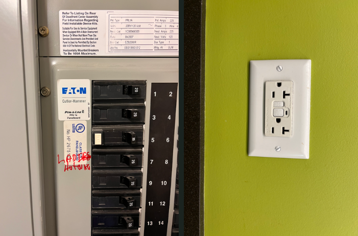 Figure 4: Layered personnel protection — an upstream arc fault circuit interrupter breaker feeding a downstream ground fault circuit interrupter receptacle. Courtesy: CDM Smith
Medium-voltage systems: protection as a stability function
Medium-voltage electrical systems generally operate between 1 and 35 kilovolts and form the backbone of distribution networks, sitting as the intermediary between high-voltage transmission and low-voltage use. Here protection is not only a safety measure; it is the mechanism that keeps the distribution structure standing and expensive equipment alive.
Why isolation matters more at medium voltage
Utility grids and power plants handle immense loads, so fault isolation is critical: a single fault in one medium-voltage circuit can cascade through the distribution system and cause outages and damage beyond the point of origin. Circuit breakers, fuses, relays and other protective devices are the first line of defence, limiting fault currents and isolating the faulted section so generators, transformers and switchgear are not what fails. Repair cost, plant operations and ultimately grid reliability and resilience trace back to that isolation.
Protective relays: the sensing and decision layer
Relays act as the brain of medium-voltage protection, continuously monitoring current, voltage and frequency and isolating the circuit when a fault appears. Digital relays extend that role with fault location, event logging, remote communication and selective coordination, ensuring only the faulted circuit is removed while unaffected areas keep service. If relay operation is inaccurate, protection becomes slow and ineffective, jeopardising equipment and personnel safety alike.
Selective coordination: a method you can reuse on any system
Coordination is the practice that turns a pile of devices into a system. It combines technical discipline with practical skill: downstream devices clear localised problems while upstream devices hold. Engineers build it from time-current curves and selective settings, balancing speed against reliability and safety. Poor coordination produces exactly the expected penalty — unnecessary outages, extra stress on equipment and avoidable loss of supply — which is why it is treated as a design deliverable rather than a commissioning afterthought.
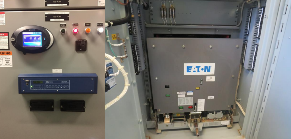 Figure 5: Medium-voltage switchgear with a digital protective relay and a draw-out breaker working together to detect faults, isolate selectively and preserve distribution reliability. Courtesy: CDM Smith
Self-healing behaviour in smart grids
Automation and real-time analytics now enter medium-voltage protection as systems transition to smart grids. Self-healing networks use sensors, relays and automated switches to detect a fault and reroute power within several cycles, drastically shorting outage durations and improving resilience against natural disasters or equipment failures. The same instrumentation enables preventative maintenance and load management, making protection part of a more sustainable and efficient energy infrastructure rather than a static safety add-on.
Common misconceptions
- "If the breaker trips, nobody can be shocked." Overcurrent devices respond to current magnitude; leakage on the order of 4 to 6 milliamperes will not move one. Personnel protection is the GFCI's job.
- "Fuses are legacy parts." They are still chosen where simplicity, no moving parts, low cost and speed under short-circuit conditions matter, including utility distribution and substation equipment.
- "The faster everything trips, the better." Instantaneous operation on harmless temporary spikes creates downtime; the thermal element's delay is a feature, and coordination exists to keep only the faulted section out of service.
- "One device type covers all hazards." Arc faults need waveform analysis, surges need clamping and diversion, ground paths need imbalance detection; overcurrent protection alone leaves much of the threat surface untouched.
- "Resettable means maintenance-free." Breakers require periodic testing precisely because their trip mechanism is mechanical.
A reusable protection review checklist
- Classify each circuit against the four fault mechanisms: sustained overcurrent, a low-resistance bridge, an unintended path to ground, and a sudden voltage rise.
- Confirm every OCPD rating matches the conductors and load it protects, then decide whether a fuse or a breaker fits the maintenance and downtime profile of that asset.
- Assess arc-fault exposure: wiring that can age or be damaged, and connections that can loosen without drawing trip-level current.
- Verify GFCI coverage in wet or damp locations and record the imbalance threshold in the design documentation.
- Specify SPDs at the service entrance or distribution panel by nominal discharge current, voltage protection level and maximum continuous operating voltage.
- Plot the time-current curves for the device stack and confirm the downstream device clears first.
- For sections between 1 and 35 kilovolts, list the relay functions in use — fault location, event logging, remote communication, selective coordination — and the isolation boundary each one controls.
- Schedule periodic testing of mechanical trip mechanisms, and revisit coordination whenever a feeder or load changes.
FAQ
What is the practical difference between a fuse and a circuit breaker?
Both interrupt overcurrent. A fuse sacrifices a calibrated element through heating and must be replaced after it clears a fault; a breaker uses thermal and magnetic mechanisms and can be reset once the cause is corrected, at the price of greater complexity, cost and periodic testing.
Are overcurrent devices enough to protect people?
No. Fuses and breakers react to current magnitude, whereas a GFCI reacts to the imbalance between outgoing and returning current and interrupts at typically 4 to 6 milliamperes — which is why damp-location receptacles depend on it.
What does an AFCI detect that a breaker cannot?
High-frequency components in the 40 to 100 kilohertz range that characterise series or parallel arcing. Such arcing can occur at currents well below what would trip an overcurrent device, so the fire risk is invisible to the breaker.
Where do surge protection devices belong?
At service entrances or distribution panels, so energy from lightning strikes or utility switching is diverted before it reaches sensitive downstream equipment.
Why does medium-voltage protection need relays rather than breakers alone?
Because the objective is selective isolation of the smallest faulted section in a network where a cascading failure is the real cost. Relays sense current, voltage and frequency and coordinate breaker operation, preserving supply for unaffected areas.
How quickly can a self-healing network respond?
Sensors, relays and automated switches can detect a fault and reroute power within several cycles, which is what shortens outage duration and strengthens resilience.
Protection as a design habit
Viewed as a discipline instead of a component list, circuit protection is the practice of deciding in advance what should be allowed to fail, how quickly, and in which order. Overloads, short circuits, ground faults, arc faults and overvoltage each demand a different sensing principle and a different response time, and it is the layering of fuses, circuit breakers, GFCIs, AFCIs, SPDs and protective relays that keeps service continuity while hazards are removed. For engineers working across residential, commercial, industrial and utility contexts, the transferable skill is not choosing a device but building the coordination logic around it — because every watt in a modern power system depends on protections whose robustness, and increasingly whose intelligence, determines how reliable the power-dependent future can be.