
Electronicseng Semiconductors: A DRV103 Open-Load Diagnostic Using a Wired-or Status Line
For compact PWM drive designs in semiconductor-controlled loads, a driver may already contain useful protection paths yet still fail to report a disconnected output. The note below explains how a small detection arrangement can make that condition visible by reusing a shared status signal. It is written for engineers evaluating the DRV103 in solenoid or power-load applications where load continuity is part of the diagnostic plan.
Baseline fault reporting in the 103
According to the source datasheet description, the DRV103 is presented as a mostly complete method to drive solenoids and power loads. Its built-in diagnostic suite includes over-current and over-temperature detection and protection. If an energize command triggers one of those covered faults, the logic-level Status OK flag output goes to 0. In that respect, the original 103 behavior does not need redesign for those known error modes.
The open-load fault reporting gap
The missing case described in the source material is open-load fault detection and reporting. Open-load can mean the driven load has become detached, lost its connection to the power source, has an open coil winding, or has another loss of continuity. When such a break is present, the driver may still receive an energize command, but the output path cannot deliver a useful load action. The original DRV103 path is said not to send a useful diagnostic error indication before or after that failed attempt, so the controller may continue operating without knowledge of the break.
Proposed compact modification
The modification is shown in Figure 1. It adds a status-reporting path based on whether V+ is present at the output when the command input is commanded low.
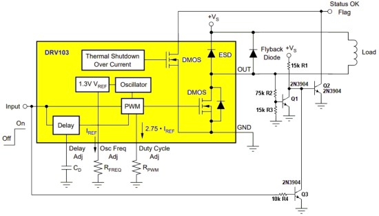
Figure 1 When Input = 0, Q2 pulls the wired-or Status OK bit low if V+ is absent at OUT, indicating an open-load condition. A connected GPI pin should be configured for passive pullup.
How the detection sequence works
- Command transition: the controller pulls Input low, typically a microcontroller general-purpose output bit.
- Transistor response: Q3 turns off and releases the collector of Q1.
- Driver state: a low Input also turns the DRV104 internal transistors off, allowing OUT to float high or low according to the connection to V+ through an intact load path.
- Healthy-load state: if V+ reaches OUT through a good load connection, Q1 turns on, Q2 turns off, and Status OK is released.
- Fault state: if the load connection is open, the absence of V+ at OUT prevents that release, allowing Q2 to assert the wired-or Status OK low.
Comparison of diagnostic coverage
| Scenario | Unmodified 103 behavior | Behavior with the Figure 1 addition |
|---|---|---|
| Over-current event during energize | Status OK output goes to 0 | Existing baseline coverage remains relevant |
| Over-temperature event during energize | Status OK output goes to 0 | Existing baseline coverage remains relevant |
| Load detached, open coil, or continuity loss | No diagnostic indication is described for the failed energize attempt | When Input = 0, Q2 can pull wired-or Status OK low if V+ is absent at OUT |
| Intact load path from OUT to V+ | No additional open-load status is described | Q1 turns on, Q2 turns off, and Status OK is released |
Implementation checklist
- Use a GP input configured for passive pullup where the wired-or Status OK signal is monitored.
- Drive the Input pin low only from a controller output that can reliably assert the 0 logic level required by the circuit description.
- Verify OUT sees the load path when Input is low; if no V+ is present because the load is detached or open, the fault branch is exercised.
- Keep the original over-current and over-temperature behavior in the test plan; the modification is aimed at the open-load reporting gap.
Common misconceptions
- Assuming Status OK high before a command guarantees that the load remains connected after the command. The source notes that an unmodified path may not report a failed energize attempt caused by an open load.
- Treating the existing protections as universal. The over-current and over-temperature suite addresses those conditions; the open-load case is called out separately.
- Ignoring the GPI pullup requirement. The figure note explicitly requires a connected GPI pin to be set up for passive pullup in the wired-or arrangement.
FAQ
What fault is being added? The added reporting path addresses open-load faults: detached load, lost power-source connection, open coil winding, or another continuity loss.
Which DRV103 status line is reused? The wired-or Status OK bit. The circuit asserts it low when the open-load condition is detected by the proposed arrangement.
Why is Figure 1 important? It shows the relationship between Input, OUT, Q1, Q2, Q3, and the shared Status OK signal.
Is DRV104 mentioned here? Yes. The operation section states that a low Input also turns the DRV104 internal transistors off.
Action recommendations
For engineers who need to decide whether this small modification is appropriate for their design, the following guidance follows directly from the described circuit behavior.
- Adopt the Figure 1 addition when the DRV103 must communicate load-open conditions to a controller, not only over-current or over-temperature faults.
- Set the monitored GPI as a passive-pullup input before relying on the wired-or Status OK release behavior.
- Test both the command-low healthy path and the command-low open path, checking that OUT sees V+ through a properly connected load and that the open path produces the Status OK low condition.
Conclusion
The modification gives a compact way to expose the open-load condition using the existing wired-or Status OK signal, while preserving the driver baseline fault suite. For design teams working with solenoids or other power loads, the main takeaway is to match the diagnostic coverage to the actual failure modes: over-current and over-temperature are covered, open-load continuity is not automatically covered unless this reporting path is added.