
Melexis MLX92342 as a Diagnostic Semiconductor for Remote Automotive Position Detection
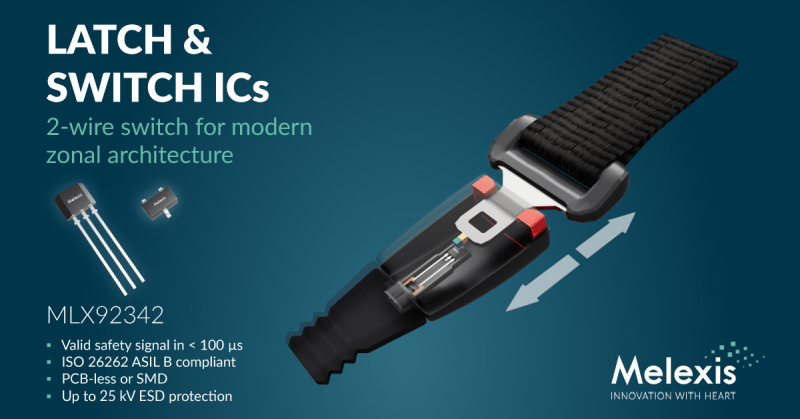
When an automotive semiconductor is evaluated for position detection, engineers often face two different questions at once. They need to know whether the physical mechanism has moved to the expected state, and they need to know whether the sensing element itself is still behaving correctly. The Melexis MLX92342 is described in the source as a programmable Hall switch for remote position detection, with the example of a seatbelt buckle. Its interface is presented as a 2-wire, PCB-less sensor IC, and its behavior is separated into a valid output and a diagnostic safety signal. That structure gives semiconductor, hardware, and system teams a compact way to discuss sensor-state reporting without treating every switch edge as an unconditional application fact.
Separating Position State From Sensor Trustworthiness
A magnetic switch output can look simple in a schematic, but the meaning of a transition depends on the context. If a buckle is engaged, the output change is an application state. If a sensor fault causes the same output change, the same bit would be misleading. The source description of MLX92342 ties these two meanings together by stating that the device supplies a valid output and produces a diagnostic safety signal in less than 100 µs. The diagnostic signal is described as marking a fault condition, so an ECU can identify a sensor fault rather than accepting the output as a normal position reading.
This is the point at which the part becomes relevant beyond a basic Hall switch: the reported state and the reported health of the sensor are available as different information streams within the same device description. For an application architect, the design task then includes how the ECU will use that separation. The source does not define the software debounce policy, the vehicle-level failure reaction, or the diagnostic message path, so those elements remain integration decisions rather than device-level facts.
2-Wire Interface as a Compact Sensing Path
The source calls the MLX92342 a 2-wire, PCB-less sensor IC. For a selection discussion, that wording places the part in a category of remote magnetic position detection where the designer is not given a wide multi-signal interface in the source. The engineering interpretation is therefore bounded: it describes the device's compact interface style, but it does not replace the need to define current consumption, voltage supply, line protection, connector loading, or board or harness layout, because those details are outside the supplied source.
The 2-wire framing is useful when comparing candidate sensing paths. It lets a project team ask whether a system can accept a single compact magnetic sensing channel while still gaining diagnostic separation. If the answer is no, because the architecture already has a different signal or power budget, the part may still be appropriate in another location. If the answer is yes, the remaining questions are magnetic, timing, qualification, and software behavior.
Qualification Anchors and What They Mean in a Review
The source lists two standards-related anchors: ISO 26262 ASIL B SEooC and AEC-Q100. It also connects these anchors to integrated on-chip diagnostics: because the device contains integrated on-chip diagnostics, the source states that it is certified as an ISO 26262 ASIL B SEooC and qualified to AEC-Q100. That causal link should be preserved in any internal design note: the diagnostic claim is not a stand-alone marketing label, but the stated basis for the safety-element context in the source.
From a component qualification view, AEC-Q100 is presented as an automotive qualification anchor. From a functional safety view, ISO 26262 ASIL B SEooC is presented as the safety-element context. Neither anchor is described in the source as a final system safety case. For a team preparing a technical assessment, the practical use of these labels is to route the device into the correct review lanes: automotive qualification, safety-element development assumptions, integration hazard analysis, and application-level verification.
ESD Robustness Figures for System Mapping
The source gives ESD ratings of 8-kV HBM, 15-kV system-level contact discharge, and 25-kV system-level indirect discharge. Those three figures serve different conversation roles. HBM is a device-level handling concern; the two system-level figures are described in the source as system-level ESD performance. The source does not describe the board, enclosure, cable, connector, or discharge network that produced the system-level context, so the figures should be mapped into a vehicle or module test plan before they are treated as proof for a particular layout.
A useful way to read the ESD paragraph is to keep each claim scoped. A design review can confirm that the source claims 8-kV HBM, 15-kV system-level contact discharge, and 25-kV system-level indirect discharge. A separate review can decide whether those claims, together with the application's mounting location and touch risk, are sufficient for the target system. That keeps the semiconductor data anchored while avoiding invented protection assumptions.
Magnetic Operating Modes and Field Range
The source states that magnetic latch, unipolar switch, and omnipolar switch configurations are supported, with a magnetic operating range of 0.5 mT to 200 mT. These details matter because a Hall switch is not selected only by part number; it is selected by the field pattern produced by the mechanism. A latch-oriented application may need a state that persists after field polarity changes. A unipolar application may be defined by one field direction. An omnipolar application may respond according to field presence rather than direction as described by the mode name. The source provides the mode list and the range, while the mechanism designer supplies the field geometry.
The 0.5 mT to 200 mT range is the most compact quantitative anchor for field selection. It can be placed into a magnet and flux calculation, but it does not by itself solve tolerance stack-up, temperature effects, magnet aging, or assembly variation. Those are system-level considerations. The source gives the operating window, and the project must show that its worst-case field remains inside that window across the intended detection event.
Application Examples Named by the Source
Seatbelt buckle detection is the first application named by the source, but it is not the only one. The device is also described as usable in window lifters, brake fluid level sensors, active air skirts, locks, valves, and actuators. The list is broad enough to show the part's remote position detection fit, yet narrow enough to require case-by-case integration planning. Each named application has a different mechanical context: a buckle state, a window travel position, a fluid level condition, an air skirt position, a locked or unlocked state, a valve state, or an actuator state.
The source also compares the device's role with designs that rely on mechanical microswitches, reed switches, or less advanced magnetic switches. For those designs, MLX92342 is described as adding programmability, diagnostics, and contactless operation. This comparison is useful because it focuses on the architectural change rather than only on magnetic sensitivity: the stated difference is not merely a new switch type, but a switch type with a programmable and diagnostic character.
Reference Data Table
| Data point from source | Verbatim or near-verbatim anchor | Review purpose |
|---|---|---|
| Manufacturer and part | Melexis MLX92342 | Identifies the semiconductor device under discussion. |
| Interface structure | 2-wire | Frames the sensing channel as a compact two-terminal source statement. |
| Timing and diagnostic behavior | less than 100 µs | Connects valid output and diagnostic safety signal to a bounded interval. |
| Safety-element context | ISO 26262 ASIL B SEooC | Places the device into a functional-safety review lane. |
| Automotive qualification | AEC-Q100 | Supports component qualification discussion. |
| ESD robustness | 8-kV HBM | Device-level handling claim. |
| ESD robustness | 15-kV system-level contact discharge | System-level ESD claim to be mapped into integration. |
| ESD robustness | 25-kV system-level indirect discharge | System-level ESD claim to be mapped into integration. |
| Magnetic window | 0.5 mT to 200 mT | Basis for flux and mechanism checks. |
| Availability | now | Source states current availability. |
| Variant | MLX92341 | Locked, pre-programmed version named by the source. |
Comparison Table
| Comparison point | Source-stated MLX92342 behavior | Application to named switch alternatives |
|---|---|---|
| Diagnostic separation | Supplies a valid output and produces a diagnostic safety signal in less than 100 µs | The source says the device can add diagnostics for designs relying on mechanical microswitches, reed switches, or less advanced magnetic switches. |
| Operating style | Programmable Hall switch | Programmability is the stated advantage over the named alternative styles. |
| Electrical framing | 2-wire sensor IC | The comparison does not define the alternative parts' electrical architecture. |
| Contact behavior | Contactless operation is listed as an added capability | It is the capability the source uses to contrast with designs using mechanical microswitches, reed switches, or less advanced magnetic switches. |
| Safety context | ISO 26262 ASIL B SEooC and AEC-Q100 are source anchors | These anchors apply to the semiconductor device, not automatically to every ECU, buckle, lock, valve, or actuator assembly. |
Engineering Checklist
- Confirm that the target position event can be expressed by magnetic latch, unipolar switch, or omnipolar switch as described in the source.
- Verify that the expected magnetic field remains within 0.5 mT to 200 mT across the intended detection motion.
- Check how the ECU consumes a valid output and a diagnostic safety signal produced in less than 100 µs.
- Keep the 2-wire, PCB-less source description aligned with the real connector, harness, and mounting layout.
- Record ISO 26262 ASIL B SEooC and AEC-Q100 as device-level qualification anchors, not as a complete system safety argument.
- Map 8-kV HBM, 15-kV system-level contact discharge, and 25-kV system-level indirect discharge into the module-level ESD verification plan.
- Decide whether the programmable MLX92342 or the locked, pre-programmed MLX92341 better matches production configuration control.
FAQ
What makes the MLX92342 different from a simple position switch?
The source states that it supplies a valid output and produces a diagnostic safety signal in less than 100 µs. The diagnostic safety signal is used to mark a fault condition, allowing the ECU to distinguish a sensor malfunction from a valid position reading.
Is seatbelt buckle detection the only application?
No. Seatbelt buckle detection is named as an example, but the source also lists window lifters, brake fluid level sensors, active air skirts, locks, valves, and actuators.
Which magnetic modes are covered?
The source states that magnetic latch, unipolar switch, and omnipolar switch configurations are supported, with a magnetic operating range of 0.5 mT to 200 mT.
What ESD figures are given?
The source gives 8-kV HBM, 15-kV system-level contact discharge, and 25-kV system-level indirect discharge.
Does the part have a safety and automotive qualification anchor?
Yes. It is described as certified as an ISO 26262 ASIL B SEooC and qualified to AEC-Q100.
Is there a pre-programmed variant?
The source states that a locked, pre-programmed version, MLX92341, is also available.
Common Misconceptions
- Assuming that any valid switch edge proves a correct mechanism state. The source separates the valid output from a diagnostic safety signal, and the diagnostic signal marks a fault condition.
- Assuming that the 2-wire description defines the entire installation. The source identifies the interface style, but not the connector, harness, supply, or layout details.
- Assuming that ISO 26262 ASIL B SEooC and AEC-Q100 make an ECU assembly automatically compliant. The source presents them as device-level anchors.
- Assuming that 0.5 mT to 200 mT solves every magnet design. It states the magnetic operating range, while the application still needs to demonstrate its field behavior inside that range.
- Assuming that contactless operation removes all integration work. It is a stated advantage over the alternatives named in the source, not a substitute for system verification.
Action Recommendations
- Begin a selection review by matching the mechanism to one of the source-stated modes: magnetic latch, unipolar switch, or omnipolar switch.
- Place the 0.5 mT to 200 mT range into the flux-budget worksheet and test the worst-case field condition.
- Model the ECU behavior around two source-stated outputs: a valid output and a diagnostic safety signal in less than 100 µs.
- Keep the 2-wire, PCB-less description tied to the physical integration, including connector and mounting decisions that are outside the source.
- Enter ISO 26262 ASIL B SEooC and AEC-Q100 into the component qualification matrix, then trace them through the target assembly.
- Compare 8-kV HBM, 15-kV system-level contact discharge, and 25-kV system-level indirect discharge against the planned ESD verification approach.
- If production needs a fixed configuration, evaluate MLX92341; if development needs programmability, evaluate MLX92342.
The source concludes that the device is available now. For engineering planning, the relevant decision is whether the described combination of remote position detection, diagnostic safety behavior, magnetic modes, qualification anchors, and ESD claims fits the selected automotive application.