
Electronicseng Semiconductors: Raltron RXF two filters for LEO satellite ground RF paths
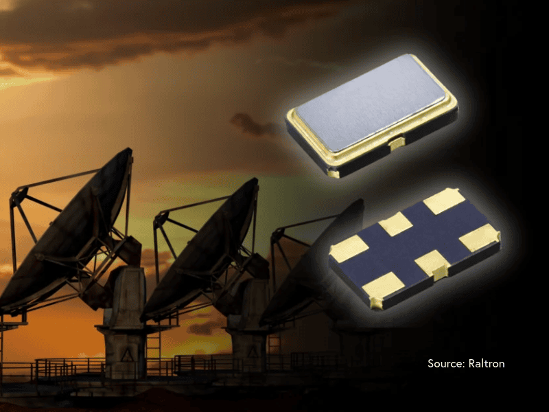
When LEO broadband networks are designed at ground level, filtering choices are often read through interface placement, receiver stability and mechanical constraints rather than through constellation architecture. The Raltron announcement described here focuses on that narrower design surface: two filters, named in the RXF family, that are offered for RF and intermediate-frequency (IF) paths in ground terminals and gateways. The original technical framing was written for eeNews Europe readers; Electronicseng Semiconductors turns it into an engineering checklist for placement in user terminals, gateway stations and control subsystems.
What this Electronicseng brief keeps intact
This brief keeps the published data points separate from design advice. The manufacturer name, model codes, nominal frequency values and the executive quotation are reproduced exactly, while the sections around them are rewritten for Electronicseng Semiconductors readers who need to know where to place the part, what to question, and what not to infer.
Component facts cited in the announcement
- Device family: RXF monolithic crystal filters from Raltron.
- Frequency options: 100 MHz and 150 MHz.
- Deployment context: ground-based equipment for LEO satellite broadband networks.
- Signal-path role: frequency selectivity in RF and IF chains.
- Design constraint addressed: compact footprint for size, weight and power (SWaP) limits.
- Environmental framing: suitable discussion for outdoor communication systems and continuous-duty expectations mentioned in the quote.
The list above is deliberately narrow. The announcement does not present a new constellation technology; it presents filtering parts inside ground equipment. That distinction matters because the reader’s next action is schematic placement, not network planning.
Data citation table: values to keep in the design note
| Cited item | Cited value | Engineering reading |
|---|---|---|
| Filter family | RXF series | Extends frequency-control work into filtering. |
| Models | two models: RXF-100.000-20-6035-6-4 and RXF-150.000-15-7050-6-2 | The decision starts with the two nominal frequency choices. |
| Nominal frequency | 100 MHz and 150 MHz | Match to RF or IF path requirements. |
| Stated performance framing | low insertion loss and stable frequency response | Relevant to predictable receive chains. |
| Package framing | compact packages | Relevant when board space and SWaP are tight. |
| Application scope | LEO ground equipment supporting Ku- and Ka-band networks | Not presented as direct microwave filtering. |
From a design-note perspective, the cited values can be split into three layers. The first layer is identity: family, models and nominal frequency. The second layer is electrical framing: low insertion loss and stable response. The third layer is mechanical and deployment framing: compact packages for ground systems. Keeping those layers separate helps prevent a compact package from being mistaken for a performance guarantee.
Model comparison: where the crystal filters differ
Both entries are presented as compact monolithic crystal filtering options for controlled response in ground hardware, so the clearest difference in the cited data is the nominal frequency. The following comparison keeps the model names intact for traceability.
| Comparison point | RXF-100.000-20-6035-6-4 | RXF-150.000-15-7050-6-2 |
|---|---|---|
| Nominal frequency | 100 MHz | 150 MHz |
| Stated type | monolithic crystal filter | monolithic crystal filter |
| Stated filter benefit | low insertion loss with stable response | low insertion loss with stable response |
| Placement mentioned | RF or IF signal path | RF or IF signal path |
| Hardware context | ground-based LEO broadband equipment | ground-based LEO broadband equipment |
| Design constraint | compact footprint | compact footprint |
Because the table above uses the same wording for both entries outside frequency, procurement teams should not read the comparison as implying different insertion-loss numbers, different package dimensions or different environmental ratings. The cited text only differentiates the nominal frequency and the corresponding part code.
Integration checklist for ground terminals and gateway stations
Use the list below as a quick design review when deciding whether these parts belong in the current schematic.
- Confirm that the host function is ground-based hardware, including user terminals and gateway infrastructure.
- Map the proposed insertion point inside a receiver chain or IF chain.
- Identify whether the board belongs to customer-premises equipment with phased-array or flat-panel antennas, gateway antenna systems, ground stations, or networking and control subsystems.
- Check whether the stage near the filter is amplification, conversion, or processing, because the cited function is suppressing unwanted signals before those stages.
- Review board space, weight and power margins before accepting the compact package claim as an advantage.
- Read the Ku- and Ka-band wording as network context rather than as a claim that the part directly filters those microwave frequencies.
A useful way to audit the checklist is to ask where the signal chain would have been less stable without frequency selectivity. The described purpose is to suppress unwanted signals before amplification, conversion or processing, so the component should be evaluated in the context of the surrounding stages rather than as a standalone block.
Why the announcement places the filters on the ground side
President of Raltron Sasha Wolloch said: “As providers scale LEO satellite broadband networks, the user terminals and gateway ground stations connecting subscribers to those constellations must deliver increasingly stable RF performance across Ku- and Ka-band frequencies under continuous-duty outdoor conditions,”. That sentence sets the engineering problem on the terrestrial side of the link: the filtering parts are discussed as ground-equipment components, while the network context is Ku- and Ka-band operation.
The phrase “continuous-duty outdoor conditions” ties the component discussion to equipment that remains deployed and operational, while “Ku- and Ka-band frequencies” identifies the network context. The combination explains why stable ground-side RF performance is mentioned without turning the crystal filters into microwave front-end devices.
Common misconceptions to test before design-in
For readers who review component news quickly, the most likely misunderstanding is band confusion. The article repeatedly anchors the parts to RF and IF paths, then mentions Ku- and Ka-band networks as the broader ground-system environment. Separating those two levels keeps the brief useful.
| Misconception | Cited correction |
|---|---|
| These are microwave Ku- or Ka-band filters. | The source positions them for ground-based systems that support Ku- and Ka-band satellite networks, rather than for direct filtering at those microwave frequencies. |
| Small package alone proves the part fits the chain. | The package claim is linked to SWaP constraints; response stability and insertion loss still need evaluation in the intended RF or IF path. |
| Either model can be dropped into either chain. | The two models are presented at 100 MHz and 150 MHz, so the nominal frequency needs to match the signal-path plan. |
FAQ: component questions that follow the cited data
Are these devices intended for satellites themselves?
No. The described application is ground-based hardware for LEO satellite broadband networks, including user terminals and gateway infrastructure.
What nominal frequencies are named?
The cited options are 100 MHz and 150 MHz.
Which part numbers should be kept in the bill-of-materials comparison?
The two models are RXF-100.000-20-6035-6-4 and RXF-150.000-15-7050-6-2.
What does the compact footprint claim solve?
It is presented as a way to help engineers meet size, weight and power constraints in satellite ground equipment.
Can this note be treated as a qualification result?
No. It is a product-positioning note based on the published component description; design teams still need to verify performance, environment and system-level margins.
Why do model numbers matter?
They preserve traceability to the cited family and allow design notes to distinguish the 100 MHz entry from the 150 MHz entry.
What should not be inferred from “compact packages”?
That the filter automatically solves all size, weight and power issues; the claim is that the compact footprint is intended to help engineers meet such constraints.
Action recommendations for design and procurement
- Start with the two models table and choose the nominal frequency that matches the planned RF or IF stage.
- Place the candidate in a schematic review before layout, because the cited role is frequency selectivity in receiver and IF chains.
- Record the low-insertion-loss and stable-response claims as requirements to verify, not as substitutes for measurement.
- Use the compact-package statement in board-space discussions, but keep the outdoor continuous-duty context separate from environmental qualification.
- Consult Raltron’s crystal filter portfolio for additional technical information when preparing the detailed selection note.
For supply-chain work, the same table can be used to prevent part-code ambiguity during requests. For hardware work, the checklist can become the first page of a design review note. In both cases, the cited model names and nominal frequencies should remain unchanged.
For Electronicseng Semiconductors readers, the useful takeaway is narrow and component-focused: the announcement describes two filters with 100 MHz and 150 MHz nominal frequencies, a compact package claim, and a ground-equipment use case tied to LEO broadband infrastructure. The value of the RXF series should therefore be judged by how well its frequency, insertion-loss expectation and footprint fit a specific user terminal, gateway antenna subsystem, ground station or control path, while the Ku- and Ka-band reference remains network context rather than a direct microwave-filtering claim.
In short, Electronicseng Semiconductors treats the announcement as a component-placement note: two filters, two model codes, two nominal frequencies, one compact-package claim and one ground-equipment application context. That is enough to guide an initial review, but not enough to claim a performance improvement without the published technical information and system-level verification.